Drilling vs Tapping vs Counterbore vs Countersink vs Reaming: What's the Difference
A poorly machined hole can compromise an entire precision component. On an engineering drawing, callouts such as Ø8 ↧20, M8 × 1.25-6H ↧15, ⌴Ø15 ↧9, and Ø10H7 may look similar, but they specify different hole features and machining requirements. This guide explains the five essential hole-making operations, their machining principles, and the correct hole machining process order.
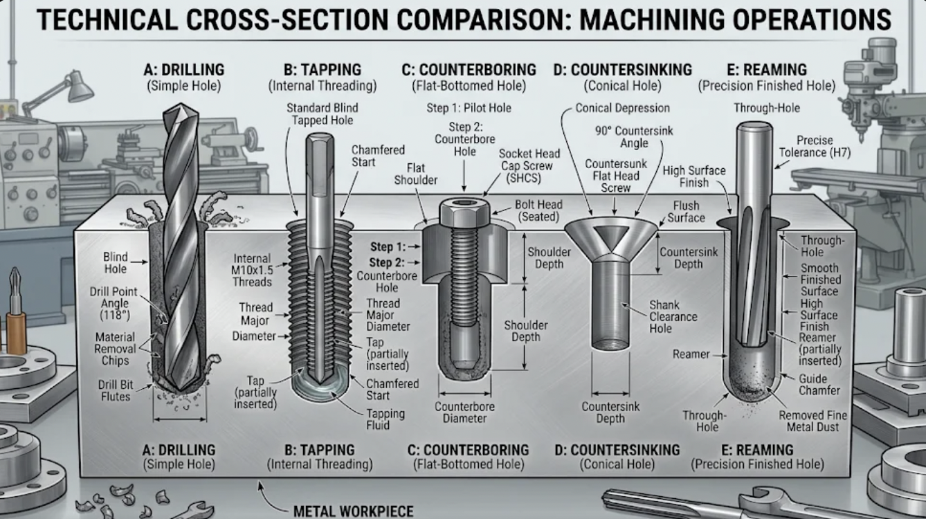
Drilling vs Tapping vs Counterboring vs Countersinking vs Reaming: Key Differences?
Whether you are designing custom CNC machined components or preparing a manufacturing process plan, understanding these operations helps improve hole accuracy, assembly quality, and machining efficiency. The first thing to understand is that these five terms describe hole-making operations, not five interchangeable types of holes. Each process uses a different cutting tool and changes a different part of the workpiece.
| Machining Process | Main Tool | Primary Function | Feature Produced | Typical Drawing Callout |
|---|---|---|---|---|
| Drilling | Twist drill bit | Creates a hole in solid material | Through hole, blind hole, tap drill hole | Ø8 ↧20 |
| Tapping | Cutting tap or forming tap | Produces internal threads | Threaded hole | M8 × 1.25-6H ↧15 |
| Counterboring | Counterbore cutter with pilot | Creates a flat-bottom cylindrical recess | Counterbore | ⌴Ø15 ↧9 |
| Countersinking | Countersink cutter | Creates a conical recess | Countersink | ⌵Ø16 × 90° |
| Reaming | Hand or machine reamer | Finishes an existing hole to a more accurate size | Precision bore | Ø10H7 |
Three important principles help distinguish these operations:
1. Drilling creates the initial hole. Drilling is the standard process for producing a hole in solid material. Tapping, counterboring, countersinking, and reaming generally require a pre-existing hole.
2. Tapping and reaming serve different purposes. Tapping produces an internal thread for a screw or bolt, while reaming improves the dimensional accuracy and surface finish of a precision bore, such as a dowel pin hole. They are generally separate finishing routes for different hole functions.
3. Counterboring and countersinking modify the hole entrance. Both can be combined with other hole features when the fastener or assembly design requires a recessed screw head or a particular seating surface.
There are also three related machining operations worth understanding:
Boring: Enlarges an existing hole and can improve its diameter, straightness, and position.
Chamfering: Removes sharp edges around a hole and provides a lead-in for tapping or assembly.
Spotfacing: Produces a shallow, flat seating surface around a hole, especially on rough, cast, or angled surfaces.
One important terminology distinction: the Chinese term "沉孔" should not always be translated as "counterbore." A flat-bottom cylindrical recess is a counterbore, a conical recess is a countersink, and a shallow flat seating area is a spotface. Also, boring and counterboring are different machining operations.
Hole Machining Sequence: What Comes First?
counterboring, countersinking, reaming, drilling and tapping are not simply five interchangeable operations. They are selected according to the function, geometry, and tolerance requirements of the hole. Most hole machining projects follow one of three general process routes.
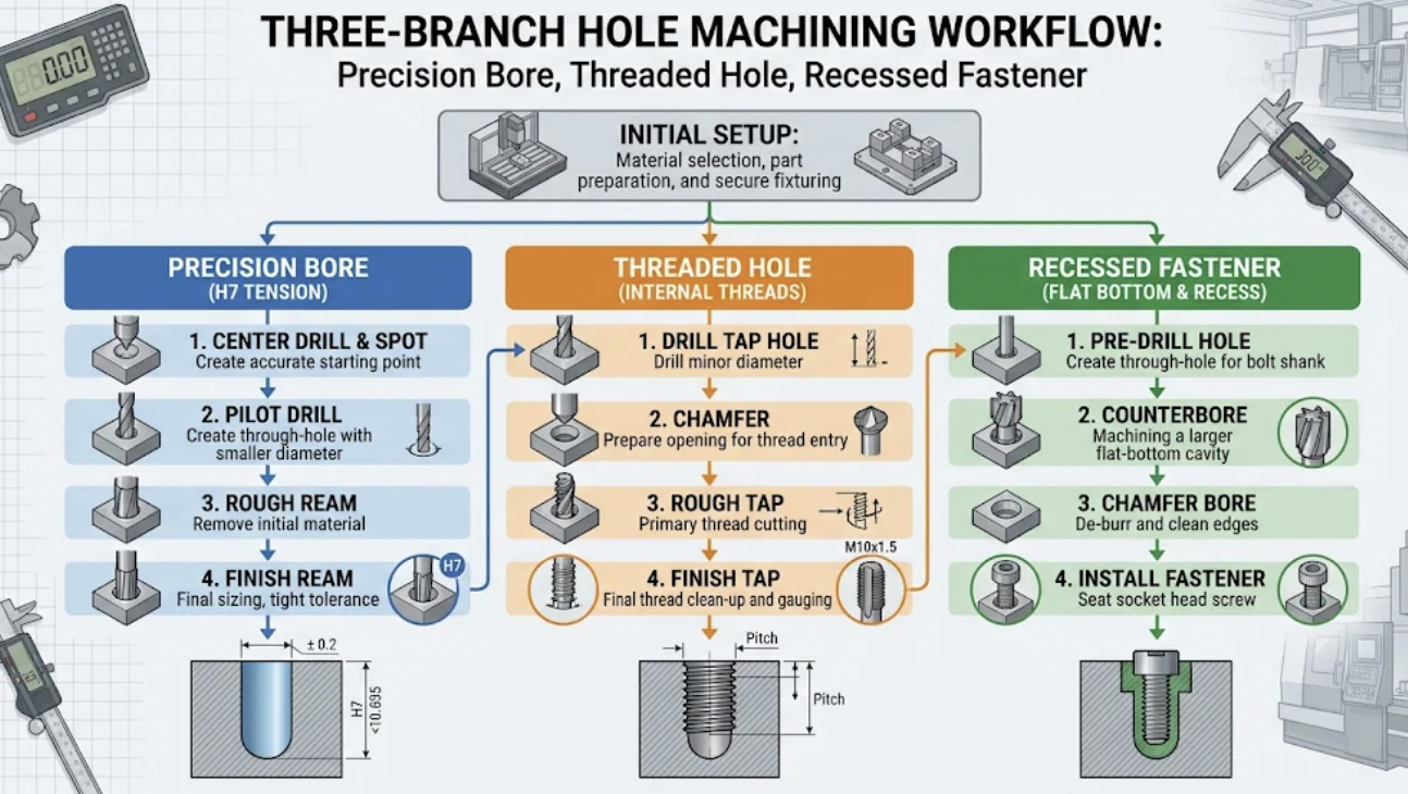
Route A: Precision Hole Machining
For precision locating holes, dowel pin holes, and fitted components, a typical machining sequence is:
Spot Drilling → Undersize Drilling → Boring or Hole Preparation → Rough Reaming (if required) → Finish Reaming
The initial hole must be prepared with sufficient machining allowance for the reamer. If the hole requires strict positional accuracy, boring or CNC interpolation may be necessary before final reaming. A typical finished hole callout is Ø10H7, where H7 represents the specified hole tolerance zone under ISO 286.
Route B: Threaded Hole Machining
For internal threaded holes, the typical process is:
Drilling → Chamfering → Tapping → Thread Inspection
The tap drill size depends on the nominal thread diameter, thread pitch, material, and tapping method.
For standard ISO metric cutting taps, a commonly used starting formula is:
Tap Drill Diameter ≈ Major Thread Diameter − Thread Pitch
For example, an M8 × 1.25 thread generally uses a 6.8 mm tap drill.
Blind holes need additional drilling depth to accommodate the tap lead and chip clearance.
Route C: Counterbored or Countersunk Holes
For fasteners that need to sit flush with or below the workpiece surface, the machining sequence may be:
Drilling → Counterboring or Countersinking → Deburring → Fastener Installation
Counterboring creates a cylindrical, flat-bottom recess for socket head cap screws. Countersinking creates a conical recess for flat-head screws.
These operations can also be incorporated into threaded-hole or precision-hole machining routes. Their exact sequence depends on the drawing, tool access, and workholding setup.
Three Important Rules for Hole Machining
1. Chamfering is normally performed before tapping.
A small chamfer at the hole entrance helps guide the tap into the hole, reduces the risk of thread damage, and removes sharp edges.
2. Reaming requires a properly prepared hole.
A reamer removes only a small amount of material. The initial drilled hole must have sufficient and reasonably consistent machining allowance. Depending on the required tolerance, boring or an intermediate enlargement operation may be necessary.
3. Reaming does not correct significant hole-position errors.
A reamer generally follows the existing hole axis. If the initial hole is incorrectly positioned, boring, CNC interpolation, or improved workholding should be used to correct the geometry before final reaming.
Drilling: Creating a Hole from Solid Material
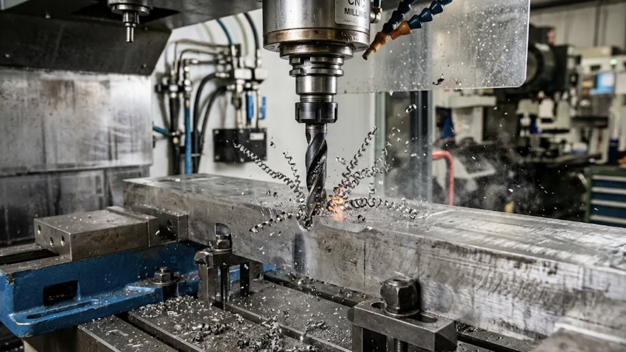
Drilling is one of the most fundamental hole-making operations in CNC machining. A rotating twist drill feeds axially into a workpiece, removing material through its cutting edges while its helical flutes evacuate chips.
A standard twist drill commonly uses a 118° point angle for general-purpose applications. Harder materials may require 130°–140° point angles, depending on the drill geometry, coating, and machining conditions.
Drilling is generally considered a rough machining operation. Typical drilled-hole accuracy may fall around IT11–IT13, with surface roughness around Ra 6.3–12.5 µm. Actual results depend on the material, machine rigidity, tool condition, and cutting parameters.
Common Drilling Applications
Producing through holes for bolts and fasteners.
Creating blind holes for threaded connections.
Preparing tap drill holes before tapping.
Producing initial holes for boring and reaming.
Creating oil passages and other functional holes in mechanical components.
Important CNC Drilling Considerations
Tool positioning: Spot drilling or another positioning method can help reduce drill wandering and improve hole location.
Workpiece clamping: Rigid workholding helps minimize vibration and movement during drilling.
Cutting speed and feed rate: Parameters should be selected according to the workpiece material, drill diameter, tool coating, and machine capability.
Chip evacuation: Peck drilling is commonly used for deeper holes to improve chip removal and reduce the risk of tool damage.
Blind-hole depth: A standard twist drill produces a conical bottom rather than a flat bottom. The drill point length must be considered when calculating the required hole depth.
On CNC machines, drilling cycles such as G81 and G83 are commonly used for standard drilling and peck drilling operations. For selecting the correct drill diameter, machinists may refer to a drill bit size chart covering metric, fractional, number, and letter drill sizes.
Tapping and Tap Drill Size Chart (Metric and UNC)
Tapping, also called thread tapping, is the process of producing internal threads in a pre-drilled hole using a cutting or forming tap. A typical tap contains three main sections:
Cutting lead: Gradually engages the material and establishes the thread profile.
Calibration section: Guides the tool and helps produce the required thread dimensions.
Flutes: Provide space for chip formation and evacuation in cutting taps.
Standard ISO metric threads generally have a 60° thread profile.
Types of Tapping Tools
There are two main categories of taps.
Cutting Taps
Cutting taps remove material to create internal threads. Common types include:
Straight-flute taps: General-purpose applications.
Spiral-flute taps: Particularly useful for blind holes because they help pull chips toward the hole entrance.
Spiral-point taps: Push chips forward and are commonly used for through-hole tapping.
Form Taps (Roll Taps)
Form taps create threads through plastic deformation rather than conventional material removal. They do not produce conventional cutting chips and are suitable for ductile materials.
However, form taps generally require larger pre-drilled holes than cutting taps. Always check the tool manufacturer's recommendations before selecting the drill diameter.
Other CNC threading methods include rigid tapping, floating tap holders, and thread milling.
How to Calculate Tap Drill Size
For standard ISO metric cutting taps, the approximate tap drill size can be calculated using:
Tap Drill Diameter ≈ Major Thread Diameter − Thread Pitch
Where:
Major thread diameter is the nominal external diameter of the thread.
Thread pitch is the distance between adjacent thread crests.
Tap drill diameter is the approximate diameter of the pre-drilled hole.
For example, an M8 × 1.25 thread requires:
8 − 1.25 = 6.75 mm
A 6.8 mm drill is commonly selected.
For an M8 × 1.0 fine thread:
8 − 1.0 = 7.0 mm
A 7.0 mm drill is a common starting choice.
Form taps require a different calculation and should be selected using the manufacturer's drill-size chart. A tap drill that is too small increases cutting torque and the risk of tap breakage. A hole that is too large reduces thread engagement and can result in weak threads.
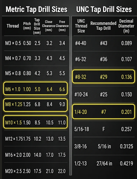
Metric Tap Drill Size Chart (M3–M20)
The following table provides commonly used drill sizes for standard metric coarse-thread cutting taps.
| Metric Thread | Pitch (mm) | Tap Drill Size (mm) | Close Clearance Hole (mm) | Free Clearance Hole (mm) |
|---|---|---|---|---|
| M3 × 0.5 | 0.50 | 2.5 | 3.2 | 3.4 |
| M4 × 0.7 | 0.70 | 3.3 | 4.3 | 4.5 |
| M5 × 0.8 | 0.80 | 4.2 | 5.3 | 5.5 |
| M6 × 1.0 | 1.00 | 5.0 | 6.4 | 6.6 |
| M8 × 1.25 | 1.25 | 6.8 | 8.4 | 9.0 |
| M10 × 1.5 | 1.50 | 8.5 | 10.5 | 11.0 |
| M12 × 1.75 | 1.75 | 10.2 | 13.0 | 13.5 |
| M16 × 2.0 | 2.00 | 14.0 | 17.0 | 17.5 |
| M20 × 2.5 | 2.50 | 17.5 | 21.0 | 22.0 |
Note: These are common reference sizes. Clearance hole dimensions depend on the selected fit and applicable fastener standard. Confirm thread engagement and drill size against the tap manufacturer's recommendations.
UNC Tap Drill Size Chart
For American manufacturing applications, the Unified National Coarse (UNC) thread system is commonly used. Unlike metric threads, UNC thread pitch is expressed as threads per inch (TPI).Some commonly used UNC tap drill combinations are listed below.
| UNC Thread Size | Recommended Tap Drill | Decimal Drill Diameter (in) |
|---|---|---|
| #4-40 | #43 | 0.089 |
| #6-32 | #36 | 0.107 |
| #8-32 | #29 | 0.136 |
| #10-24 | #25 | 0.150 |
| 1/4-20 | #7 | 0.201 |
| 5/16-18 | F | 0.257 |
| 3/8-16 | 5/16 in | 0.3125 |
| 1/2-13 | 27/64 in | 0.4219 |
For example, the commonly searched 1/4-20 UNC tap drill size is a #7 drill bit with a diameter of approximately 0.201 inches. For an 8-32 UNC thread, the commonly selected tap drill is a #29 drill bit with a diameter of approximately 0.136 inches.
Blind Hole Tapping: Drill Depth and Tool Selection
Blind hole tapping requires more attention than through-hole tapping because chips can accumulate at the bottom of the hole. The total drilling depth must be greater than the required full thread depth to accommodate the tap lead and chip clearance.
A preliminary process-planning estimate is:
Drill Depth = Required Full Thread Depth + Tap Lead Allowance + Chip Clearance
The additional depth depends on the tap geometry, pitch, hole diameter, and material. A rough allowance of 2–3 thread pitches for the tap lead and additional chip space can be used as an initial reference, but should not replace the tap manufacturer's recommendations.
Important considerations include:
Use spiral-flute taps when chip evacuation toward the hole entrance is required.
Use spiral-point taps mainly for through holes where chips can move forward.
Consider bottoming taps when threads are required closer to the bottom of a blind hole.
Chamfer the hole entrance before tapping.
Select suitable cutting fluid for the workpiece material.
Use rigid tapping or an appropriate floating tap holder when required.
Maintain alignment between the tap and the pre-drilled hole.
A typical metric internal thread callout is:
M8 × 1.25-6H ↧15
This indicates an M8 internal thread with a 1.25 mm pitch, 6H tolerance class, and a specified thread depth of 15 mm. For a more extensive drill and tap reference, see Dajin Precision's Drill Bit and Tap Size Chart.
Counterbore vs Countersink: What's the Difference?
Counterboring and countersinking are secondary hole machining operations used to prepare a hole entrance for fasteners. Although both operations create space for screw heads, they produce different geometries and serve different assembly requirements.
countersink vs counterbore
The difference between a counterbore and a countersink is primarily the shape of the recess.
Counterboring
A counterbore creates a cylindrical, flat-bottom recess at the top of an existing hole. It is commonly used for socket head cap screws, such as those specified under ISO 4762 or DIN 912, allowing the screw head to sit flush with or below the workpiece surface. A counterbore cutter often uses a pilot to guide the tool through the existing hole and maintain concentricity.
Countersinking
A countersink creates a conical recess at the entrance of an existing hole. It is commonly used for flat-head screws that need to sit flush with the surrounding surface. The countersink angle must match the fastener head angle to provide proper seating and contact.
Counterbore, Countersink, and Spotface Symbols
Engineering drawings use specific symbols to communicate hole geometry and machining requirements.
| Symbol | Meaning | Example |
|---|---|---|
| ⌴ | Counterbore symbol | ⌴Ø15 ↧9 |
| ⌵ | Countersink symbol | ⌵Ø16 × 90° |
| ⌴ with SF | Spotface notation in applicable drawing conventions | ⌴Ø20 SF |
| ↧ | Depth symbol | Ø8 ↧20 |
A spotface is a shallow, flat machining operation that creates a perpendicular seating surface around a hole. It is particularly useful on castings, forgings, and angled or uneven workpiece surfaces. The difference between a spotface and a counterbore is their intended depth and function:
A counterbore creates a controlled recess to accommodate a fastener head.
A spotface removes only enough material to create a flat seating surface.
Countersink Angle: 82° vs. 90°
The countersink angle must match the fastener head geometry. Common included angles include:
82°: Commonly used for inch-standard flat-head screws.
90°: Commonly used for metric and ISO-style flat-head fasteners.
100°: Used in some aerospace and specialized fastening applications.
60°, 110°, and 120°: Used in other specialized applications.
Using an 82° screw with a 90° countersink can result in improper contact between the screw head and the workpiece. This may cause uneven seating, reduced contact area, and poor assembly performance. Always check the fastener specification before selecting the countersink cutter.
Typical Metric Counterbore Dimensions
The following reference dimensions are based on the metric socket head cap screw series cited in the original source (GB/T 152.3). They should be checked against the applicable current standard and fastener manufacturer's specifications before production.
| Screw Thread | Through Hole Diameter dh (mm) | Counterbore Diameter D (mm) | Counterbore Depth H (mm) |
|---|---|---|---|
| M3 | 3.4 | 6 | 4 |
| M4 | 4.5 | 8 | 5 |
| M5 | 5.5 | 10 | 6 |
| M6 | 6.6 | 11 | 7 |
| M8 | 9.0 | 15 | 9 |
| M10 | 11.0 | 18 | 11 |
| M12 | 13.5 | 20 | 13 |
| M14 | 15.5 | 24 | 15 |
| M16 | 17.5 | 26 | 17 |
As a preliminary design reference:
Counterbore diameter is often approximately 1–2 mm larger than the screw head diameter.
Counterbore depth should accommodate the screw head height plus the required clearance.
The counterbore should remain concentric with the original hole.
The fastener should be test-fitted when necessary.
An excessively deep counterbore may bury the screw head too far below the surface, while insufficient depth can leave the screw head protruding.
Reaming vs Drilling: What's the Difference?
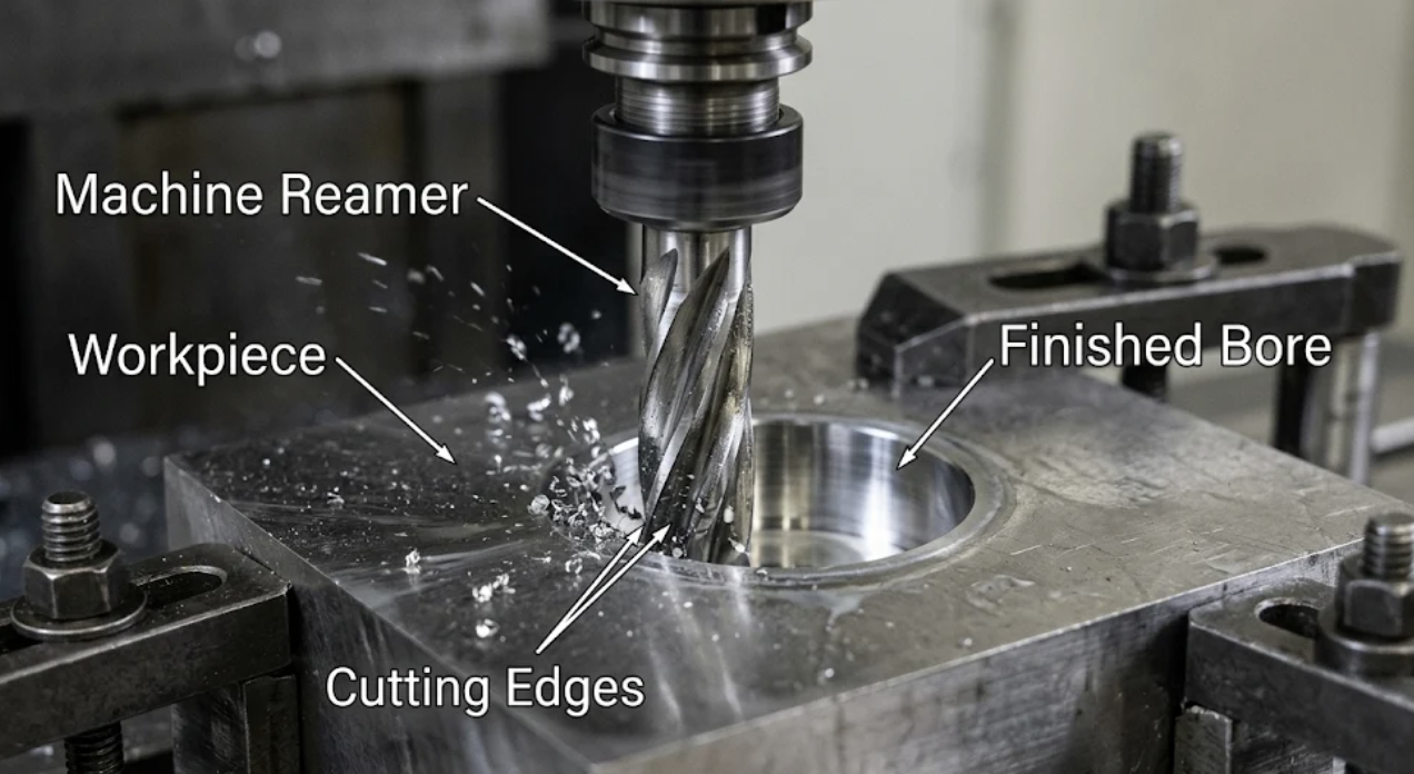
Drilling vs reaming: Reaming is a finishing operation that improves the dimensional accuracy and surface quality of an existing hole. The main difference between drilling and reaming is the amount of material removed and the purpose of the operation. Drilling creates an initial hole in solid material. Reaming removes a small amount of material from a pre-drilled or otherwise prepared hole to improve its diameter, roundness, and surface finish.
Types of Reamers
Common reamer types include:
Hand reamers: Used for manual finishing and controlled hole sizing.
Machine or chucking reamers: Designed for machining operations on drilling machines, CNC machines, and other machine tools.
Spiral-flute reamers: Help with chip evacuation in blind or interrupted holes, depending on their design.
Adjustable reamers: Allow limited diameter adjustment for specific applications.
Typical Reaming Accuracy and Surface Finish
Depending on the workpiece material, tool geometry, machine rigidity, and machining conditions, reaming may achieve IT7–IT9 dimensional accuracy, with finer results possible in suitable applications.
Typical surface roughness may fall around Ra 0.2–1.6 µm. An H7 precision hole is a common engineering requirement for dowel pins, locating features, and precision-fit components. For example:
Ø10H7. This indicates a nominal hole diameter of 10 mm with an H7 tolerance zone under ISO 286.
Reaming Allowance: How Much Material Should Be Removed?
Reaming allowance refers to the material intentionally left in an existing hole for removal during the reaming process. The original hole should not be drilled directly to the final reamed diameter without considering the required machining allowance. The following values are general starting references:
| Reaming Stage | Approximate Allowance Per Side | Total Diametral Allowance |
|---|---|---|
| Rough reaming | 0.15–0.35 mm | 0.30–0.70 mm |
| Finish reaming | 0.05–0.15 mm | 0.10–0.30 mm |
| Typical total allowance | 0.10–0.25 mm | 0.20–0.50 mm |
These values are not universal machining specifications. The correct allowance depends on hole diameter, material, initial hole quality, reamer geometry, and the tool manufacturer's recommendations. Too much machining allowance can increase cutting forces, cause chatter, and reduce tool life. Too little allowance can cause the reamer to rub instead of cut, resulting in poor surface finish and inconsistent hole dimensions.
Important Reaming Rules
1. Reaming does not correct hole position.
A reamer generally follows the existing hole axis. If the hole is off-position, boring or CNC interpolation should be considered before final reaming.
2. Do not reverse the spindle while the reamer is engaged.
Unless the tool manufacturer specifies otherwise, withdraw the reamer in its cutting direction to avoid damaging the cutting edges or finished hole surface.
3. Maintain proper lubrication and chip evacuation.
Clean coolant, suitable lubrication, and effective chip removal help prevent built-up edges, chatter marks, and oversized holes.
4. Select the correct reamer geometry.
Different reamer designs are intended for different materials, hole conditions, and machining applications. Tool selection should reflect the required hole tolerance and surface finish.
Engineering Drawing Hole Symbols and Callouts
Understanding engineering drawing symbols is essential for selecting the correct hole machining operation. A small difference in a drawing callout can change the required tool, machining sequence, and final hole geometry.
| Symbol or Notation | Meaning | Example | Related Machining Process |
|---|---|---|---|
| Ø | Diameter | Ø8 | Drilling / Reaming |
| ↧ | Depth | Ø8 ↧20 | Blind-hole drilling |
| M | ISO metric thread | M8 × 1.25 | Tapping |
| 6H / 6g | Internal / external thread tolerance class | M8-6H | Thread machining |
| ⌴ | Counterbore | ⌴Ø15 ↧9 | Counterboring |
| ⌵ | Countersink | ⌵Ø16 × 90° | Countersinking |
| H7 | Hole tolerance zone under ISO 286 | Ø10H7 | Precision hole machining |
| Ra | Surface roughness parameter | Ra 1.6 | Surface finishing |
| ⌖ | True position tolerance symbol | Position Ø0.02 | CNC positioning / inspection |
The most frequently confused symbols are the counterbore symbol ⌴ and the countersink symbol ⌵.A counterbore specifies a cylindrical, flat-bottom recess, whereas a countersink specifies a conical recess. Misinterpreting either symbol can lead to incorrect hole geometry and fastener seating problems.
Common Hole Machining Defects and How to Fix Them
Even when the correct machining process is selected, incorrect tooling, cutting parameters, or process sequencing can cause quality problems. The following table summarizes common hole machining defects, their possible causes, and recommended corrective actions.
| Common Defect | Possible Cause | Recommended Solution |
|---|---|---|
| Broken tap or damaged threads | Tap drill hole too small, insufficient lubrication, poor chip evacuation, or misalignment | Verify tap drill size, chamfer the hole, use suitable cutting fluid, and select the correct tap geometry |
| Weak or shallow threads | Tap drill hole too large | Recheck drill diameter and required thread engagement |
| Chatter marks or oversized reamed holes | Incorrect reaming allowance, tool runout, built-up edges, or dirty coolant | Optimize allowance, inspect tool runout, and improve coolant and chip evacuation |
| Hole remains off-position after reaming | Expecting reaming to correct the original hole location | Use boring or accurate CNC positioning before reaming |
| Counterbore is not concentric with the hole | Poor tool guidance or multiple setups | Use a guided counterbore cutter and maintain accurate workholding |
| Screw head protrudes or sits too deep | Incorrect counterbore depth | Verify fastener head dimensions and counterbore specifications |
| Flat-head screw does not seat correctly | Mismatched 82° and 90° countersink angles | Match the countersink angle to the fastener specification |
| Full thread does not reach the required depth | Drilling only to the specified full thread depth | Allow additional depth for the tap lead and chip clearance |
Proper process planning, suitable cutting tools, and accurate workholding are essential for reducing machining defects and maintaining consistent hole quality.
How to Choose the Right Hole Machining Process?
The correct hole machining process depends on the function of the hole, not simply its diameter. The following table provides common applications and recommended machining sequences.
| Hole Requirement | Recommended Machining Sequence | Typical Drawing Callout |
|---|---|---|
| Standard bolt clearance hole | Drilling | Ø9 |
| Internal threaded connection | Drilling → Chamfering → Tapping | M8 × 1.25-6H ↧15 |
| Recessed socket head screw | Drilling → Counterboring | ⌴Ø15 ↧9 |
| Flush-mounted flat-head screw | Drilling → Countersinking | ⌵Ø16 × 90° |
| Precision dowel pin hole | Drilling → Boring / Ream Preparation → Reaming | Ø10H7 |
| Strict positional accuracy or large non-standard bore | Boring / CNC interpolation → Finishing | Ø30H7, position Ø0.02 |
Whether you need drilled holes, threaded features, precision bores, or complex machined components, send your drawings and project requirements to Dajin Precision for a manufacturing evaluation. Explore Dajin Precision CNC Machining Services or contact our team to discuss your custom machining project.